Thermal Oxidation
What is it?
Thermal oxidation (also often referred to as 'incineration', 'thermal incineration' or 'oxidative combustion') is the oxidation process of combustible gases and odorants in a waste gas stream by heating a mixture of contaminants with air or oxygen above its auto ignition point in a combustion chamber and maintaining it at a high temperature for sufficient time to complete combustion to carbon dioxide and water.
After thermal oxidation, the main constituents of the treated waste gas are water vapour, nitrogen, carbon dioxide and oxygen. Depending on the pollutant content of the raw waste gas being incinerated and on the operating conditions of the thermal oxidiser, other pollutants may be present in the treated waste gas such as CO, HCl, HF, HBr, HI, NOX, SO2, VOCs, PCDDs/PCDFs, PCBs, and heavy metal compounds (among others). It may require upstream treatment depending on the raw waste gas composition or additional downstream treatment of the treated waste gas.
Depending on the combustion temperatures during the main stages of incineration, volatile heavy metals and inorganic compounds (e.g. salts) are totally or partially evaporated. These substances are transferred from the input waste to both the treated waste gas and the fly ash it contains. A mineral residue fly ash (dust) and heavier solid ash (bottom ash) are created.

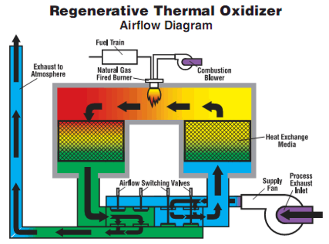
Figure 1. Scheme of a regenerative thermal oxidiser

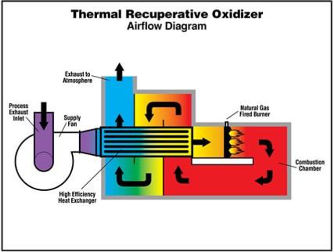
Figure 2. Scheme of a recuperative thermal oxidiser
Time, temperature (about 200–400 °C above auto ignition), turbulence (for mixing) and the availability of oxygen all affect the rate and efficiency of the combustion process. These factors provide the basic design parameters for VOC/ odour oxidation systems.
Several types of thermal oxidisers are operated:
Several types of thermal oxidisers are operated:
- The straight thermal oxidiser, comprised of a combustion chamber and not including any heat recovery of flue-gas.
- The regenerative thermal oxidiser(Figure 1), using the following steps:
- waste gas stream entering the oxidiser through the common inlet and passing into a regenerative chamber through a butterfly valve;
- then passing through a ceramic heat exchange matrix, which raises the gas temperature almost to oxidation temperature;
- then entering the combustion chamber, which is maintained at 800–1000°C by burners, the released heat decreasing the fuel consumption of the burners;
- then leaving the combustion chamber through a second ceramic heat exchanger matrix, transferring its thermal energy to be reused for preheating the next cycle;
- releasing the clean gas stream through an outlet valve to discharge.
- The recuperative thermal oxidiser (Figure 2), comprised a combustion chamber, the waste gas preheater and, if appropriate, a secondary energy recovery heat exchanger, the heat continuously transferred to the preheater. This system is particularly suitable for waste gas stream flow rates in the range of 1000–50000 Nm3/h. Generally, 50–80% heat recovery is achieved.
- Gas engines and/or steam boilers, with 57–67% energy recovery. The waste gas is burnt in the engine. The concentration of the inlet gas has to be controlled to ensure that it is burnt efficiently in the engine. If necessary, natural gas can be added as support fuel or the waste stream may need to be diluted. Downstream generators produce electricity. The engine contains a catalytic converter, principally to oxidise the carbon monoxide in the gas stream. The engine is coupled with a steam boiler to use the waste heat of the flue-gas for the production of steam. The boiler feed water is preheated by the engine cooling water. With low combustion temperatures, the formation of NOX is low. The flue-gas leaving the gas engine is led over oxidation catalysts to reduce the carbon monoxide content.
This system is particularly suitable for waste gas streams with flow rates in the range of 5,000–10,000 Nm3/h. Generally, 90–97% heat recovery (waste gas preheating) is achieved.
Design, maintenance and efficiency
The design criteria for a thermal oxidiser system depend mainly on the nature of the waste gas stream (i.e. chemical and physical characteristics such as particle size, composition, and also thermal characteristics such as calorific value and moisture level), which determines the combustion conditions.
Thermal oxidisers should be inspected regularly and, if necessary, cleaned to maintain good performance and efficiency. When excess depositions occur, preventive actions have to be taken by cleaning the incoming gas before it enters the oxidiser.
Monitored parameters which should trigger an alarm when set values are exceeded include:
- combustion temperature;
- concentration of VOCs;
- concentration of carbon monoxide;
- pressure;
- feed of liquefied gas;
- feed of compressed air.
Applicability
Table 1 shows application limits and restrictions associated with thermal oxidation (adapted from EIPPCB, 2016, Table 3.204).
Table 1. Application limits and restrictions associated with thermal oxidation.
Table 1. Application limits and restrictions associated with thermal oxidation.
| Issue | Limits/ Restrictions |
|---|---|
| Gas flow (Nm3/h) | 90-86000 (straight and regenerative oxidiser) 90-86000 (recuperative thermal oxidiser) |
| Temperature (°C) | 900-1200 |
| Pressure (MPa) | Atmospheric |
| Pressure drop (mbar) | 10 - 50 |
| Particulate content (Nm3/h) | <3 |
| Residence time(s) | 0.5-2 |
| Relative humidity of the waste gas | max 70% |
